Group 4: Difference between revisions
No edit summary |
No edit summary |
||
| Line 118: | Line 118: | ||
\left|\frac{d\phi}{d\tau}\right|\to\gamma\left|\frac{d\phi}{d\tau}\right|+c | \left|\frac{d\phi}{d\tau}\right|\to\gamma\left|\frac{d\phi}{d\tau}\right|+c | ||
\end{equation} | \end{equation} | ||
This nature of the escapement mechanism and the validity of this model is perhaps most visible for very low frequencies, as seen in the following video. Notice the behavior of the pendulum around $\phi=0$. | |||
<videoflash>zBvBpVtrjA8</videoflash> | |||
With a complete theoretical model, we must estimate the values of our parameters before we can fully construct a computer simulation of the experiment. | With a complete theoretical model, we must estimate the values of our parameters before we can fully construct a computer simulation of the experiment. | ||
| Line 129: | Line 134: | ||
As far as the parameters corresponding to the modeling of the escapement mechanism are concerned, $\gamma$ is difficult to estimate, but $c$ can be predicted fairly well. For $c$, this is because it is primarily the magnitude of this kick that determines the amplitude of the pendula after several oscillations; we experimentally observe oscillations in the range of about $45^{\circ}$, so we can adjust the value of $c$ accordingly. For our simulation, we have decided to use $\gamma=0.97$ and $c=0.025$, as was used in Wiesenfeld and Borrero-Echeverry\cite{Borrero}. | As far as the parameters corresponding to the modeling of the escapement mechanism are concerned, $\gamma$ is difficult to estimate, but $c$ can be predicted fairly well. For $c$, this is because it is primarily the magnitude of this kick that determines the amplitude of the pendula after several oscillations; we experimentally observe oscillations in the range of about $45^{\circ}$, so we can adjust the value of $c$ accordingly. For our simulation, we have decided to use $\gamma=0.97$ and $c=0.025$, as was used in Wiesenfeld and Borrero-Echeverry\cite{Borrero}. | ||
The pendulum length l, the final remaining parameter, is difficult to estimate because of a simplification in the model, different from the metronome we use in our experiment. The simulation models a pendulum with a point mass, $m$, a distance $l$ from the pivot. The metronome, in reality, has two spatially extended masses located at two different distances from the pivot. An attempt to calculate an equivalent distance resulted in $l=0.025 m$; however, this gives a natural frequency for the simulation that is considerably higher than what is experimentally observed. The simulation was run a second time with a new value of $l=0.1m$ to match the natural frequency of the | The pendulum length l, the final remaining parameter, is difficult to estimate because of a simplification in the model, different from the metronome we use in our experiment. The simulation models a pendulum with a point mass, $m$, a distance $l$ from the pivot. The metronome, in reality, has two spatially extended masses located at two different distances from the pivot. An attempt to calculate an equivalent distance resulted in $l=0.025 m$; however, this gives a natural frequency for the simulation that is considerably higher than what is experimentally observed. The simulation was run a second time with a new value of $l=0.1m$ to match the natural frequency of the pendulums in the simulation to that of the experiment. | ||
== Simulation == | == Simulation == | ||
| Line 144: | Line 149: | ||
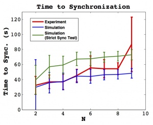
[[File:TimeToSync_SameFreq.jpg| thumb | 300px | alt = The time to synchronization for our best estimate of parameter values, with $l=10cm$. | The time to synchronization for experiment and simulation. Parameters are our ``best estimate," as indicated in the Parameters section above, with $l=10cm$. Error bars indicate one standard deviation. The natural frequencies of the simulation and experiment are approximately equal.]] | [[File:TimeToSync_SameFreq.jpg| thumb | 300px | alt = The time to synchronization for our best estimate of parameter values, with $l=10cm$. | The time to synchronization for experiment and simulation. Parameters are our ``best estimate," as indicated in the Parameters section above, with $l=10cm$. Error bars indicate one standard deviation. The natural frequencies of the simulation and experiment are approximately equal.]] | ||
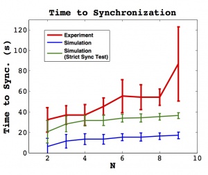
The time to synchronization for experiment and simulation is shown in | The time to synchronization for experiment and simulation is shown in the two figures to the right. | ||
Since the definition of synchronization is somewhat subjective, two synchronization tests are used for the simulation. The first, drawn in blue, uses the same criteria as for the experiment, applied to the time series of $\phi_j$ vaues. This line should be compared to the experimental result, but since the simulation is not subject to experimental error, this criteria may be too lenient. The second simulation line, drawn in green, uses a ``Strict Sync Test" to determine synchronization; the condition for synchronization in this case is that all peak values of $\phi_j$ must be within one time discretization. These two lines are intended to provide a range of simulation synchronization times depending on the stringency of criteria. | Since the definition of synchronization is somewhat subjective, two synchronization tests are used for the simulation. The first, drawn in blue, uses the same criteria as for the experiment, applied to the time series of $\phi_j$ vaues. This line should be compared to the experimental result, but since the simulation is not subject to experimental error, this criteria may be too lenient. The second simulation line, drawn in green, uses a ``Strict Sync Test" to determine synchronization; the condition for synchronization in this case is that all peak values of $\phi_j$ must be within one time discretization. These two lines are intended to provide a range of simulation synchronization times depending on the stringency of criteria. | ||
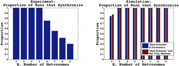
The figure below shows the proportion of runs in both the experiment and simulation that satisfy the synchronization criteria within the allotted time. The decrease in synchronization for $N>5$ in the experiment may be attributable to short data runs, typically of only 2 minutes. Had we waited longer, perhaps synchronization would have been reached; however, more than once we waited as long as the metronome winding would allow, and synchronization was not observed. For the simulation, synchronization is observed in every case except $N=2$. Although this suggests that there are some fundamentally different dynamics between the experiment and simulation, this result in the simulation may be explained as follows. Borrero-Echeverry and Wiesenfeld demonstrated (see Figure 6 of Wiesenfeld and Borrero-Echeverry\cite{Borrero}) that varying the platform damping coefficient can cause the size of the basins of attraction for in phase and antiphase synchronization to expand or contract. We believe that for our particular set of parameters, which differ from those of Wiesenfeld and Borrero-Echeverry\cite{Borrero}, a thin basin of attraction exists for the antiphase state; as we add more mass to the platform, we decrease the value of $\Gamma$ and the antiphase state is no longer an attractor for $N=3$ or higher. | |||
[[File:SyncProportion.jpg| center | 600px | alt = The time to synchronization for our best estimate of parameter values, with $l=10cm$. | The time to synchronization for experiment and simulation. Parameters are our ``best estimate," as indicated in the Parameters section above, with $l=10cm$. Error bars indicate one standard deviation. The natural frequencies of the simulation and experiment are approximately equal.]] | [[File:SyncProportion.jpg| center | 600px | alt = The time to synchronization for our best estimate of parameter values, with $l=10cm$. | The time to synchronization for experiment and simulation. Parameters are our ``best estimate," as indicated in the Parameters section above, with $l=10cm$. Error bars indicate one standard deviation. The natural frequencies of the simulation and experiment are approximately equal.]] | ||
Revision as of 02:40, 16 December 2011
Group Members: Luis Jover, Vlad Levenfeld, Brad Taylor, & Jeff Tithof
The synchronization of coupled oscillations has proven to be a useful model for describing the dynamics of a large number of physical systems. Perhaps the simplest system which can capture such dynamics is that of two oscillators coupled through the motion of a free platform. In recent years, there has been a considerable amount of research on the case of $N=2$; however, little work has extended to larger numbers of oscillators. The goal of the current work is to quantify the time to synchronization for $N=2$ through $N=9$ metronomes on a movable platform, through experimental investigation and numerical simulation. Our results show a considerable level of agreement between the two, and discrepancies are explored. Possibilites for future work and potential improvements are noted.
Background
The phenomenon of synchronization is found throughout nature and in many applications of different fields of science. Examples of synchronization include the flashing of firefly populations, the firing of pacemaker cells in the heart, applications of Josephson junctions, coupled fiber laser arrays, and perhaps even epileptic seizures. Many instances of synchronization in nature and applications in science become extremely complicated as soon as multiple variables or several coupled oscillators are introduced. However, the pervasive presence of synchronization in nature and science motivates work towards a deep understanding of such phenomena. So, as with any system that is to be scientifically understood, the simplest case is the best place to begin; for synchronization, the case of two identical, coupled oscillators is perhaps the simplest.
Research into the mutual synchonization of two identical coupled oscillators is believed to date back to the work of Christiaan Huygens in the 1600's, in which he discovered and investigated the synchronization of two pendulum clocks hanging on a common support beam. Although his goal was to solve the "Longitude Problem" at the time, he did reach some insightful conclusions about the nature of this system, eventually concluding that small movements of the support beam with every oscillation were responsible for the antiphase synchronization that consistently occurred.
Significant progress has been made in explaining simple instances of synchronization. In 2002, Bennett et al. <ref>M. Bennett, M. F. Schatz, H. Rockwood, and K. Wiesenfeld, ``Huygens's clocks," Proc. R. Soc. Lond. A 458, 563-579 (2002).</ref> constructed an apparatus meant to recreate the setup decribed by Christiaan Huygens. The experimental and numerical results agree qualitatively with records from Huygens's research. Concurrently, Pantaleone <ref>J. Pantaleone, ``Synchronization of metronomes," American Journal of Physics 70, 992-1000 (2002).</ref> investigated a similar setup in which metronomes were placed on a common support which was free to roll across cylinders, allowing coupling through the low-friction horizontal translation of the platform. Pantaleone's theoretical analysis provided agrees with the experimental observations reported.
In 2009, Ulrichs et al. <ref>H. Ulrichs, A. Mann, and U. Parlitz, ``Synchronization and chaotic dynamics of coupled mechanical metronomes," Chaos 19, 043120 (2009).</ref> reported agreement with Pantaleone's results in computer simulations. Additionally, these simulations were run for coupling of up to 100 metronomes and reportedly showed chaotic and hyperchaotic behavior. A paper by Borrero-Echeverry and Wiesenfeld <ref>Daniel Borrero-Echeverry and Kurt Wiesenfeld, ``Huygens (and Others) Revisted," Publication in progress, Obtained through personal contact (2011).</ref>, currently in the process of publication, describes a theoretical model which encompasses the behavior of both types of oscillators often studied, clocks and metronomes, which often contrast in the phase of synchronization encountered. This paper attributes the difference in synchronization phase to differences in parameters of the oscillators.
An arguably strong theoretical understanding of the $N=2$ case has been developed in recent years; it seems appropriate to expand this theory to a larger number of coupled oscillators. This is the goal of the current work.
Experiment

Below is a video of synchronization for $N=2$ in our experiment.
<videoflash>AMwDIIeacvs</videoflash>
For $N=8$, one sees that full, in-phase synchronization is not achieved in the next video. <videoflash>h1wY13XspVI</videoflash>
Theory
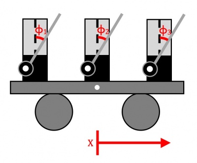
The equations of motion for two coupled pendulums are available in Bennett et al.\cite{Bennett} and Wiesenfeld and Borrero-Echeverry\cite{Borrero}. These equations may easily be extended to $N$ metronomes:
\begin{equation} \label{dim_eq1} \ddot\phi_j+b\dot\phi_j+\frac{g}{l}\sin\phi_j=-\frac{1}{l}\ddot X \cos\phi_j+F_j \end{equation}
\begin{equation} \label{dim_eq2} (M+m)\ddot X+B\dot X = -ml\frac{d^2}{dt^2}(\sin\phi_1+\sin\phi_2+ ... +\sin\phi_N) \end{equation} where $\phi_j$ is the angular displacement of the jth pendulum, $b$ is the pivot damping coefficient, $g$ is the acceleration due to gravity, $l$ is the pendulum length, $X$ is the linear displacement of the platform, $F$ is the impulsive drive, $M$ is the platform mass, $m$ is the metronome rod mass, $B$ is the platform friction coefficient, and the dots represent differentiation with respect to time.
Nondimensionalizing results in the following:
\begin{equation} \label{nondim_eq1} \frac{d^2\phi_j}{{d\tau}^2}+2\tilde\gamma\frac{d\phi_j}{d\tau}+\sin\phi_j=-\frac{d^2Y}{{d\tau}^2}\cos\phi_j+\tilde F_j \end{equation}
\begin{equation} \label{nondim_eq2} \frac{d^2Y}{{d\tau}^2}+2\Gamma\frac{dY}{d\tau}=-\mu\frac{d^2}{d\tau^2}(\sin\phi_1+...+\sin\phi_N) \end{equation}
where we have introduced the dimensionless parameters:
\begin{equation} \label{nondim_param1} \tau=t\sqrt{\frac{g}{l}} \end{equation}
\begin{equation} \label{nondim_param2} \mu=\frac{m}{M+Nm} \end{equation}
\begin{equation} \label{nondim_param3} \tilde\gamma=b\sqrt{\frac{l}{4g}} \end{equation}
\begin{equation} \label{nondim_param4} \Gamma=\frac{B}{(M+Nm)}\sqrt{\frac{l}{4g}} \end{equation}
All parameters and variables described are well defined and may be experimentally measured, with the exception of $\tilde{F_j}$, the impulsive drive of the metronome, which receives a treatment first described in [1]. The escapement mechanism which ``kicks" the metronome is mimicked in two parts: first, the angular velocity of the pendulum is slowed by some factor $\gamma$, and then, a numerical constant $c$ is added to the angular velocity:
\begin{equation} \label{kick} \left|\frac{d\phi}{d\tau}\right|\to\gamma\left|\frac{d\phi}{d\tau}\right|+c \end{equation}
This nature of the escapement mechanism and the validity of this model is perhaps most visible for very low frequencies, as seen in the following video. Notice the behavior of the pendulum around $\phi=0$.
<videoflash>zBvBpVtrjA8</videoflash>
With a complete theoretical model, we must estimate the values of our parameters before we can fully construct a computer simulation of the experiment.
Parameters
Several parameters must be estimated for use in the simulation. With the exception of gravitational acceleration and the number of metronomes, all parameters must be estimated with a varying amount of uncertainty. The platform mass contains perhaps the least uncertainty, and is given (in kilograms) by $M=0.0655+N(0.094-m)$, where we include the mass of the metronome minus the bob in the total. The pendulum bob mass is estimated as $0.022kg$; this is only estimated because an exact measurement would require the destruction of borrowed experimental materials.
The pivot damping coefficient, b, is estimated from a measurement of the decay time for an undriven oscillation of the metronome, experimentally determined as $t_{decay}=20 s$; the value used for b is thus $b=2m/t_{decay}=0.0022$. The platform damping coefficient, B, has a considerable amount of uncertainty; we expect that for our soda cans rolling on a smooth surface, the damping should be very small, so we somewhat arbitrarily pick $B=0.001$.
As far as the parameters corresponding to the modeling of the escapement mechanism are concerned, $\gamma$ is difficult to estimate, but $c$ can be predicted fairly well. For $c$, this is because it is primarily the magnitude of this kick that determines the amplitude of the pendula after several oscillations; we experimentally observe oscillations in the range of about $45^{\circ}$, so we can adjust the value of $c$ accordingly. For our simulation, we have decided to use $\gamma=0.97$ and $c=0.025$, as was used in Wiesenfeld and Borrero-Echeverry\cite{Borrero}.
The pendulum length l, the final remaining parameter, is difficult to estimate because of a simplification in the model, different from the metronome we use in our experiment. The simulation models a pendulum with a point mass, $m$, a distance $l$ from the pivot. The metronome, in reality, has two spatially extended masses located at two different distances from the pivot. An attempt to calculate an equivalent distance resulted in $l=0.025 m$; however, this gives a natural frequency for the simulation that is considerably higher than what is experimentally observed. The simulation was run a second time with a new value of $l=0.1m$ to match the natural frequency of the pendulums in the simulation to that of the experiment.
Simulation
Incorporation of the equations and the parameters listed above into a computer model allows for a simple numerical investigation for the cases of $N=2$ through $N=9$. For each case, we run 100 simulations with randomly selected initial conditions (similar to the ``random" initial conditions of the experiment) of approximately constant total energy. The equations of motion are integrated in the simulation up to $\tau=2000$, and synchronization is determined from two criteria: (1) applying the same test from the experimental determination, but applied to the simulation $\phi$ variable, and (2) applying a ``strict sync test" in which all peak $\phi$ values must be within one time discretization. Runs which fail to satisfy the criteria are noted.
Results


The time to synchronization for experiment and simulation is shown in the two figures to the right. Since the definition of synchronization is somewhat subjective, two synchronization tests are used for the simulation. The first, drawn in blue, uses the same criteria as for the experiment, applied to the time series of $\phi_j$ vaues. This line should be compared to the experimental result, but since the simulation is not subject to experimental error, this criteria may be too lenient. The second simulation line, drawn in green, uses a ``Strict Sync Test" to determine synchronization; the condition for synchronization in this case is that all peak values of $\phi_j$ must be within one time discretization. These two lines are intended to provide a range of simulation synchronization times depending on the stringency of criteria.
The figure below shows the proportion of runs in both the experiment and simulation that satisfy the synchronization criteria within the allotted time. The decrease in synchronization for $N>5$ in the experiment may be attributable to short data runs, typically of only 2 minutes. Had we waited longer, perhaps synchronization would have been reached; however, more than once we waited as long as the metronome winding would allow, and synchronization was not observed. For the simulation, synchronization is observed in every case except $N=2$. Although this suggests that there are some fundamentally different dynamics between the experiment and simulation, this result in the simulation may be explained as follows. Borrero-Echeverry and Wiesenfeld demonstrated (see Figure 6 of Wiesenfeld and Borrero-Echeverry\cite{Borrero}) that varying the platform damping coefficient can cause the size of the basins of attraction for in phase and antiphase synchronization to expand or contract. We believe that for our particular set of parameters, which differ from those of Wiesenfeld and Borrero-Echeverry\cite{Borrero}, a thin basin of attraction exists for the antiphase state; as we add more mass to the platform, we decrease the value of $\Gamma$ and the antiphase state is no longer an attractor for $N=3$ or higher.

Conclusion
We extend recent theoretical developments in the modeling of coupled oscillators beyond the $N=2$ case. We investigate the time to synchronization for $N$ coupled metronomes both numerically and experimentally, and find considerable agreement between the two, especially when the simulation parameters are altered to match the natural frequency experimentally observed. Discrepancy between simulation and experiment may be attributed to a number of factors, including but not limited to: (1) incorrect estimates of parameters, (2) experimental complexities not captured by the model (e.g. the metronome ``kick" mechanism, a reaction force from the platform, etc.), and (3) limited experimental and numerical statistics.
Future Work
Much work can be done to improve upon this effort. In particular, much work can still be done using the data we have collected. A better algorithm for determining synchronization (in place of our $\epsilon$ method) would likely give more reliable results from this data. Alternative methods include a weighted average to determine the peaks and perhaps a Fourier analysis. Further analysis of our data could extract results such as how frequency changes with $N$ or a quantification of the non-synchronized states that we observed.
In terms of extensions beyond this work, obvious improvements include a better estimate of the simulation parameters and a larger ensemble of data for stronger statistics. Additionally, one could vary any of the parameters and test the agreement between experiment and numerics. The two most appealing parameters to vary are perhaps the natural frequency of the metronomes and the platform mass.
Clearly, there is much to be learned before the phenomenon of synchronization is thoroughly understood, but a solid foundation is being constructed.
References
<references />