Group 3 2012
Chaos Circuits
Patrick Chang, Edward Coyle, John Parker, Majid Sodagar
The nonlinear dynamics of Chua’s circuit and its applications to communications is studied. Chaos is realized, and is investigated by calculating the Lyapunov exponent for the system. A three dimensional phase portrait for the characteristic “double scroll” is reconstructed from the two dimensional image, from which the correlation dimension is calculated. This experiment was done by designing Chua’s circuit in the laboratory and comparing results to a simulation.
Introduction
Chaos is aperiodic long-term behavior in a deterministic system that exhibits sensitive dependence on initial conditions [Strogatz2001]. There are many applications for chaotic systems, such as predicting nonlinear flow in the atmosphere, understanding the dynamics in cardiac arrhythmias, and handwritten character recognition. Certain studies show that a chaotic system made of circuits can produce novel musical sounds [Chua 1994]. However, in this experiment, we focus more on the applications of a chaotic system in communication. Chaotic signals are usually broad-band, noise like, and difficult to predict [Cuomo1993]. Therefore, chaotic systems are suitable for carrying information. In digital communication, sinusoidal carriers are used because they have optimal bandwidth efficiency and it is easier to reconstruct the original signal. However, their high power spectral density causes a high level of interference and enhances the probability of interception by other receivers [Arena2006]. Chaotic carriers can solve this problem. A chaotic transmitter can send the desired information masked by chaotic signals. This masked signal is then transmitted to the destination, and the signal might be intercepted on the way, but would not be decoded without the masking chaotic signal. At the destination, another chaotic signal generator will be synchronized with the chaotic signal generator at the transmitter and thus produce the exact replica of the masking chaotic signal. The masked signal will then be demodulated by subtracting the masking signal from it to reveal the desired information hidden within [Dedieu1993]. Also, broadband information carriers enhance the robustness of communication and are less vulnerable to interference from narrow-band disturbance. This is the basis of spread-spectrum communication techniques, such as the code division multiple access (CDMA) protocol used in the Global Positioning System (GPS) and in the third generation of mobile telephones [Argyris2005].
thumb|400px|alt=text|Figure 1: Two Chua Circuits on a single breadboard
In order to achieve masking information in chaotic signals to obtain secure communication, the chaotic oscillators, transmitter and receiver, must be synchronized. Initially, we wanted to achieve synchronization between two or more Chua's circuits acoustically [Harada1996] for the following reasons. Chua's circuit, introduced to the world by Leon Chua in 1983[Wikipedia], is the simplest autonomous circuit that can exhibit a bifurcation and generate chaos, because it satisfies the three criteria for displaying chaotic behavior: containing one or more nonlinear components, one or more locally active resistor, and three or more energy-storage devices [Wikipedia]. It has been a very suitable subject for studying dynamical chaos by means of both laboratory experiments and computer simulations [Harada1996]. Acoustic coupling enables us to adjust various parameters to achieve synchronization, e.g. wave amplitude, feedback time delay, characteristic of media between the oscillators, etc.
However, after setting up our circuits and the acoustic component, we found out that the parts we had are too weak to communicate with the other circuit. Instead, in the process of building up the Chua’s circuits and adjusting their parameters to find chaotic signal, we found some interesting nonlinear behavior of the Chua’s circuit. So we decided to focus on characterizing the nonlinear dynamics of the Chua’s circuit. People have been characterizing Chua’s circuits by computer simulation, so we want to do it from an experimental point of view.
Design and Parts
Chua's Circuit
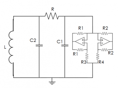
Figure 1 shows a typical Chua circuit. There are three main components to the circuit: the pair of capacitors, the inductor, and Chua's diode. Chua's diode is considered everything to the right of the C1 capacitor in Figure 1, and it is this part that causes the circuit to be nonlinear. Without this component, the circuit is a type of RLC circuit that will exhibit periodic behavior. The op-amp is used to drive the two diodes with a varying voltage. As the voltage varies, one of the diodes may cut off current going both ways if the voltage drops below the diode's cut-in voltage. This on/off behavior of the diodes drastically changes the circuit and causes chaotic behavior.
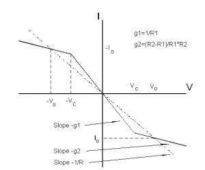
Chua’s circuit can be built several different ways. This experiment replicated the circuit diagram in Figure (1). It has four major components: (1) a variable resistor, whose resistance acts as the control variable, (2) two capacitors, whose electrical responses act as the dependent variables, (3) an inductor, and (4) Chua’s diode, which is the source of the nonlinearity in the system. The electrical response of Chua’s diode is shown in Figure (2) and corresponds to the function g(V) in the differential equations.
Figure (2) shows a picture of the circuit. Here there are actually two Chua circuits on one circuit board, but all of the experiments were carried out using only one. The project to study how two Chua circuits coupled together, either electrically or acoustically, was abandoned to study the dynamics of a single Chua circuit. As it turns out, the dynamics of a single Chua circuit are complex enough to merit further study.
Chua’s circuit was hooked up to an oscilloscope and external computer that sampled the voltages across the two capacitors at 48,000 samples per second. Data was collected for several different values of the variable resistance.
Parts
- 3 - 10 nF Capacitors
- 3 – 100 nF Capacitors
- 3 – 15 mH Inductors
- 3 – Variable Resistors in kΩ range
- 6 – 220 Ω Resistors
- 6 – 22 kΩ Resistors
- 3 – 2.2 kΩ Resistors
- 3 – 3.3 kΩ Resistors
- 6 – MA23L3 Ultrasonic Transducers (not used)
- 3 – TL082
The Equations
- <math>\frac {dx}{dt} = α[y - x - g(x)]</math>
- <math>\frac {dy}{dt} = x - y + z</math>
- <math>\frac {dz}{dt} = -βy</math>
x(t) is the voltage across C1, y(t) is the voltage across C2, and z(t) is the current across L. α and β depend on the values of the various circuit components. The function g(x) is the source of the non-linearity, and it depends on the specifications of Chua's diode. The IV curve of a Chua's Diode is shown in Figure 2, and this is the piece-wise g(x) function used in the equations. For simulations of these equations, see references [1] and [4].
Parts
- 3 - 10 nF Capacitors
- 3 – 100 nF Capacitors
- 3 – 15 mH Inductors
- 3 – Variable Resistors in kΩ range
- 6 – 220 Ω Resistors
- 6 – 22 kΩ Resistors
- 3 – 2.2 kΩ Resistors
- 3 – 3.3 kΩ Resistors
- 6 – MA23L3 Ultrasonic Transducers
- 3 – TL082
Procedure
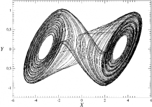
The first step in this experiment is to create a working Chua's circuit that exhibits chaotic behavior. This is measured using an oscilloscope. Chaos is achieved when the phase plane takes on a double scroll attractor, as shown in Figure 3. This can be achieved by varying the resistance of the resistor R in Figure 1. Once a Chua's circuit is successfully built, the circuit needs to be modified with an ultrasonic transducer so that the circuit produces acoustic output. Once again, chaos has to be achieved as measured by an oscilloscope. Once this is done, a duplicate will be made so that the two can become acoustically coupled. Measurements of the voltages inside both coupled circuits will be compared to see if there is any sort of synchronization.
References
Websites
    [1] http://crossgroup.caltech.edu/chaos_new/Chua.html
    [2] http://www.wellgainelectronics.com/muratama23l3.aspx
    [3] http://www.chuacircuits.com/
    [4] http://www.chuacircuits.com/sim.php
    [5] http://nonlinear.eecs.berkeley.edu/chaos/chaos.html
Literature
    [6] S. H. Strogatz, Nonlinear Dynamics and Chaos: With Applications To Physics, Biology, Chemistry, And Engineering (Studies in Nonlinearity). Westview Press, 2001, p. 512.
    [7] K. Cuomo, “Synchronization of Lorenz-based chaotic circuits with applications to communications,” Circuits and systems II: …, vol. 40, no. 10, pp. 626–633, 1993.
    [8] P. Arena, A. Buscarino, L. Fortuna, and M. Frasca, “Separation and synchronization of piecewise linear chaotic systems,” Physical Review E, vol. 74, no. 2, pp. 1–11, Aug. 2006.
    [9] A. Argyris, D. Syvridis, L. Larger, V. Annovazzi-Lodi, P. Colet, I. Fischer, J. García-Ojalvo, C. R. Mirasso, L. Pesquera, and K. A. Shore, “Chaos-based communications at high bit rates using commercial fibre-optic links.,” Nature, vol. 438, no. 7066, pp. 343–6, Nov. 2005.
    [10] Y. Harada, K. Masuda, and A. Ogawa, “Dynamical behavior of acoustically coupled chaos oscillators,” Fractals-an Interdisciplinary …, 1996.


